- 您现在的位置:买卖IC网 > Sheet目录2011 > MAX5893EGK+D (Maxim Integrated Products)IC DAC 12BIT DUAL 500MSPS 68-QFN
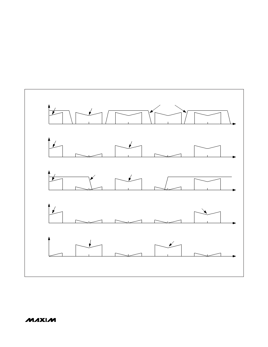
images at odd numbers of fS are filtered. At the output of
the first filter, the images are at 2fS, 4fS, etc. This signal is
then passed to the second interpolating filter, which is
similar to the first filter and removes the images at 2fS, 6fS,
10fS, etc. Finally, the third filter removes images at 4fS,
12fS, 20fS, etc. Figures 10, 11, and 12 similarly illustrate
the spectral responses when using the interpolating filters
combined with the digital modulator.
MAX5893
12-Bit, 500Msps Interpolating and Modulating
Dual DAC with CMOS Inputs
______________________________________________________________________________________
21
Figure 10. Spectral Representation of 4x Interpolation Filter with fIM/4 Modulation (Output Frequencies are Relative to the Data Input
Frequency, fS)
FOR COMPLEX MODULATION THE MODULATION SIGN (BIT 1, ADDRESS 01h) SELECTS UPPER OR LOWER SIDEBAND
LOWER
SIDEBAND
UPPER
SIDEBAND
fS
2fS
3fS
4fS
fS
2fS
3fS
4fS
fS
2fS
3fS
4fS
fS
2fS
3fS
4fS
fS
2fS
3fS
4fS
FILTER
RESPONSE
FILTER
RESPONSE
INPUT
SPECTRUM
AND FIRST
FILTER
RESPONSE
OUTPUT
SPECTRUM
OF THE
FIRST
FILTER
INPUT
SPECTRUM
AND
SECOND
FILTER
RESPONSE
OUTPUT
SPECTRUM
OF THE
SECOND
FILTER
OUTPUT
SPECTRUM
OF THE
MODULATOR
2x INTERPOLATION
4x INTERPOLATION
NO INTERPOLATION
SIGNAL
IMAGE
SIGNAL
IMAGE
SIGNAL
IMAGE
SIGNAL
IMAGE
发布紧急采购,3分钟左右您将得到回复。
相关PDF资料
MAX5894EGK+D
IC DAC 14BIT DUAL 500MSPS 68-QFN
MAX5895EGK+D
IC DAC 16BIT 500MSPS DUAL 68-QFN
MAX5898EGK+D
IC DAC 16BIT DUAL 500MSPS 68-QFN
MAX6900ETT+T
IC RTC I2C COMPAT 6-TDFN
MAX6902ETA+T
IC RTC SPI COMPAT 8-TDFN
MAX7375AXR604+T
IC OSC SILICON SC70-3
MAX7394ATTLY+T
IC OSC SILICON 922KHZ 6-TDFN
MAX7403CSA+
IC FILTER LOWPASS 8-SOIC
相关代理商/技术参数
MAX5893EGK+TD
功能描述:数模转换器- DAC 12-Bit 2Ch 500Msps DAC RoHS:否 制造商:Texas Instruments 转换器数量:1 DAC 输出端数量:1 转换速率:2 MSPs 分辨率:16 bit 接口类型:QSPI, SPI, Serial (3-Wire, Microwire) 稳定时间:1 us 最大工作温度:+ 85 C 安装风格:SMD/SMT 封装 / 箱体:SOIC-14 封装:Tube
MAX5893EGK-D
功能描述:数模转换器- DAC RoHS:否 制造商:Texas Instruments 转换器数量:1 DAC 输出端数量:1 转换速率:2 MSPs 分辨率:16 bit 接口类型:QSPI, SPI, Serial (3-Wire, Microwire) 稳定时间:1 us 最大工作温度:+ 85 C 安装风格:SMD/SMT 封装 / 箱体:SOIC-14 封装:Tube
MAX5893EGK-TD
功能描述:数模转换器- DAC RoHS:否 制造商:Texas Instruments 转换器数量:1 DAC 输出端数量:1 转换速率:2 MSPs 分辨率:16 bit 接口类型:QSPI, SPI, Serial (3-Wire, Microwire) 稳定时间:1 us 最大工作温度:+ 85 C 安装风格:SMD/SMT 封装 / 箱体:SOIC-14 封装:Tube
MAX5893EVCMOD2
功能描述:数模转换器- DAC Evaluation Kit for the MAX5893/MAX5894/MAX5895 RoHS:否 制造商:Texas Instruments 转换器数量:1 DAC 输出端数量:1 转换速率:2 MSPs 分辨率:16 bit 接口类型:QSPI, SPI, Serial (3-Wire, Microwire) 稳定时间:1 us 最大工作温度:+ 85 C 安装风格:SMD/SMT 封装 / 箱体:SOIC-14 封装:Tube
MAX5893EVKIT
功能描述:数模转换器- DAC Evaluation Kit for the MAX5893/MAX5894/MAX5895 RoHS:否 制造商:Texas Instruments 转换器数量:1 DAC 输出端数量:1 转换速率:2 MSPs 分辨率:16 bit 接口类型:QSPI, SPI, Serial (3-Wire, Microwire) 稳定时间:1 us 最大工作温度:+ 85 C 安装风格:SMD/SMT 封装 / 箱体:SOIC-14 封装:Tube
MAX5894EGK+D
功能描述:数模转换器- DAC 14-Bit 2Ch 500Msps DAC RoHS:否 制造商:Texas Instruments 转换器数量:1 DAC 输出端数量:1 转换速率:2 MSPs 分辨率:16 bit 接口类型:QSPI, SPI, Serial (3-Wire, Microwire) 稳定时间:1 us 最大工作温度:+ 85 C 安装风格:SMD/SMT 封装 / 箱体:SOIC-14 封装:Tube
MAX5894EGK+TD
功能描述:数模转换器- DAC 14-Bit 2Ch 500Msps DAC RoHS:否 制造商:Texas Instruments 转换器数量:1 DAC 输出端数量:1 转换速率:2 MSPs 分辨率:16 bit 接口类型:QSPI, SPI, Serial (3-Wire, Microwire) 稳定时间:1 us 最大工作温度:+ 85 C 安装风格:SMD/SMT 封装 / 箱体:SOIC-14 封装:Tube
MAX5894EGK-D
功能描述:数模转换器- DAC RoHS:否 制造商:Texas Instruments 转换器数量:1 DAC 输出端数量:1 转换速率:2 MSPs 分辨率:16 bit 接口类型:QSPI, SPI, Serial (3-Wire, Microwire) 稳定时间:1 us 最大工作温度:+ 85 C 安装风格:SMD/SMT 封装 / 箱体:SOIC-14 封装:Tube